Home telephone network of two telephones. Simple intercom Do-it-yourself intercom
Below are schematic diagrams and articles on the topic of “intercom” on the radio electronics website and radio hobby website.
What is an “intercom” and where is it used, schematic diagrams of homemade devices that relate to the term “intercom”.
I was born and raised in the village. Somewhere in the 50s, my village was equipped with radio. The broadcasts of the radio broadcast network began at 6 and ended at 24. But from 12.00 to 16.00 there was a break. Quite often, my friend and I... The proposed intercom (PU) is designed for loudspeaking communication between any two subscribers. It can be successfully used in the garden between the house and the gate, between two rooms, and also between... Often, when negotiating between objects, it is required that all correspondents hear the negotiations at the same time. This intercom device (PU) makes it possible to conduct such negotiations between three objects. There are often practical situations when it is necessary to control a load (for example, lighting lamps) over wires from several remote controls. The first thing that comes to mind is to solve a similar problem head-on: use a lot of wires, exactly... A simple intercom has been successfully used for conversations while driving a motorcycle. The K174UN5 microcircuit, connected according to a standard direct amplification circuit, was used as low-frequency signal amplifiers. The device consists of two of the same type... In a multi-room apartment or remote premises with increased background noise, the device proposed below will be useful. The circuit consists of one K174UN7 microcircuit. Communication mode is simplex, i.e. with “receive/transmit” switching. Switching modes... When starting work on this radiotelephone, I was given the task of creating a design that was simple to build and reliable in operation. As a result, a simple and economical radiotelephone was created, consisting of a handset and a base unit connected to a telephone line. Duplex... The developed device is intended for organizing two-way duplex radio communication in moderately rough terrain. The device can be used in construction and installation work, organizing public and sporting events, protecting objects, hunting,... Often in the practice of a novice radio amateur there is a need to assemble a simple wired intercom device, say, for a summer cottage, so that you can carry on a conversation from rooms with those who are in the kitchen, in the bathhouse, utility room or with neighbors in the country. To solve this... A diagram of a simple homemade intercom, assembled from spare parts from disassembled electronic equipment. A radio amateur differs from a normal person in that he never throws away electronic equipment, even completely unnecessary and faulty or partially functional. Anything can happen... Old TVs are gradually losing ground, ending up in dismantling, or worse - in the trash. Well, one day I came across one, well I always carry a folding screwdriver with me... One of the perfectly working boards was a ULF board. And the TV is “Selena” (“Horizon 51-TC418” ... A schematic diagram is given for converting old acoustic speakers into an intercom that can be used as an intercom. The personal computer has long and deeply penetrated our everyday life, becoming so necessary device like a TV... Schematic diagram of a home-made optical telephone using laser pointers, a simple intercom. A laser pointer can be used not only for its intended purpose. transistors, which can be used as an intercom. It would seem that now you can buy any electronic device for any household purpose. But, alas, there was a need to install an intercom on the gate on the fence of a private house... A rather unusual use of the KR142EN12A stabilizer chip. which built the circuit of a homemade intercom. Intercom for one apartment, or office, private house. There is no calling scheme; the calling scheme is a regular apartment bell, which works as an independent system. The intercom is simplex, controlled only from the apartment. On the outside there is only a speaker, also known as a microphone... The schematic diagram of a homemade intercom, which is not difficult to make, is made with four transistors. Conventional intercoms are usually designed for many subscribers and are intended for apartment buildings. But, in small towns and rural areas there are many single-family (private) houses... A simple intercom circuit based on two subscriber loudspeakers with transformers and volume controls. Single-program subscriber loudspeakers “radio points” are no longer so popular, often due to the lack of a radio network, or due to competition from VHF-FM radio broadcasting... A simple scheme for connecting two old telephone sets to organize a two-way communication line. It turned out that after the exchange apartments, two simple rotary telephones became redundant. There was no telephone point in the new apartment, and no one regretted it - everyone had cell phones. Devices... An extremely simple circuit for a homemade intercom with two transistors, a simple intercom for a summer house or a small house. An intercom is a very useful thing because it allows you to communicate with the guest before running to open the door. Intercoms in large apartment buildings still allow... Schematic diagram of a very simple homemade intercom with just one K174UN14 chip (foreign analogue - TDA2003). The intercom is designed to work in tandem with any apartment bell, that is, it does not provide a calling function. Intercom for one subscriber point, it turns out...Intercom - diagram
The personal computer has long and deeply penetrated our everyday life, becoming as necessary a device as a television. Many have already replaced their PC more than once or upgraded it. Among other things, once purchased inexpensive computer “speakers” (active speakers), at some stage ceased to meet the user’s requirements or were replaced by more expensive ones with the sound quality of a good music center.
The same story happened with my Genius SP-E120 “speakers” - they went to the back shelf, but came in handy when I needed to make a simple intercom for one subscriber.
Figure 1 shows a diagram of the Genius SP-E120 active speaker system.
As can be seen from the figure, the diagram is quite consistent with the price of this equipment. Weak ULF on a chip TEA2025, switched on according to a standard scheme, a passive volume control, and two speakers, one of which (SP1) is in the main unit, and the second in the additional one. There, in the main block, there is a board with ULF and a transformer power supply. The additional block is almost empty - there is only the SP2 speaker.
The sound quality is very mediocre, but for working as an intercom - an intercom, it is more than satisfactory.
The idea is to leave the main unit indoors and take the additional unit outside. Also add a couple of electret microphones and a blocking switch to prevent self-excitation due to acoustic feedback.
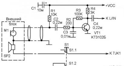
The intercom intercom circuit diagram is shown in Figure 2.

The external unit is the second speaker (which is empty), in addition you need to install an M1 electret microphone. Connection to the main unit via a cable in which one core is shielded (which carries the signal from the microphone).
S1 - “receive/transmit” switch. There is only one, and it is located only in the main block. The diagram shows it in the “reception” position, that is, when we are listening to a guest.
Power is supplied to microphone M1 through resistor R1. Since the signal level at the output of the electret microphone was not enough to supply an active speaker to the ULF input, there is an additional ULF on transistor VT1.
And so, the guest says, the signal from the microphone via cable goes first to the ULF on VT1, and then to the left channel of the speaker. From the output of the left speaker channel through S1.2, the amplified signal is supplied to the speaker SP1, located in the main unit. And we hear the guest.
To answer the guest you need to press S1. Now our speaker SP1 turns off, but speaker SP2, located in the external unit, turns on.
The signal from microphone M2 goes to the preliminary ULF on VT2 and from it to the input of the right channel of the active speaker. From the output of the right speaker channel, through S1.1, the amplified signal goes to speaker SP2, located in the external unit.
The guest hears what we tell him.
No ringing device is provided here, since there was already a regular apartment bell, and before starting a conversation the guest presses its button.
I want to admit, I initially planned to make a duplex system, since the amplifier is stereophonic, but, alas, the acoustic feedback was overcome only by the S1 switch, which turned the system into a simplex one. But that's not bad either.
I’m sure a similar device can be made from any inexpensive and no longer needed active speaker for a personal computer.
Since we live in a village and we have introduced per-minute payment for telephone calls, the question arose about creating our own connection. The intercom circuit diagram below is designed for 2 (or more) subscribers. Since both devices are identical, we will analyze the operation of only one of them. The circuit is based on a two-stage low-frequency amplifier made using transistors VT1 - VT2. A VM1-DEMSH1a microphone or any other electromagnetic type microphone is installed at the amplifier input. We used a DEMK6a telephone capsule as a load for the output stage. The metal plate E1 is used to call another subscriber. The device is powered by a stabilized power supply with an output voltage of 4.5...9 V or a Krona battery.
Details and design.
In the intercom you can use transistors MP 13-MP16, MP20, MP21, MP25, MP26, MP39 - MP42 with any letter indices. MLT resistors with a power of 0.125 W. Capacitors - any, but preferably small-sized so that the entire structure fits the 8 microphone compartment of a telephone handset.
Our design works perfectly at a distance of up to 3 km. The device does not require adjustment and, with proper installation and serviceable parts, begins to work immediately after turning on the power.
Source: D. Klimkovich, S. Belimenko, “Radio Amateur” magazine.
Related Posts
This circuit performs all the basic operations for converting parallel code into serial and transmitting data. In this case, the serial code mode and format pins are included to obtain the format…….
A special feature of this radio station is the design of the receiver and transmitter. They are functionally complete units. This makes it possible to improve the radio station by replacing them. The electrical circuit diagram of the radio station is shown in Fig.........
Traditional ohmmeters with a nonlinear scale do not allow even an approximately accurate reading of the measured resistance, especially at the edges of the scale. It is more convenient to use a device with a linear scale, and when making such an ohmmeter,…….
The radio station operates on one fixed frequency in the 27 MHz range with amplitude modulation. The range of reliable communication between two such radio stations in open areas is about 1000 m. The radio station is powered by…….
Among the types of radio stations approved by the Ministry of Communications for personal communications there is the so-called “D” type - children's intercoms, the use of which does not require special permission. Allocated for them…….
Often in the practice of a novice radio amateur there is a need to assemble a simple wired intercom, say, for a summer cottage, so that one can carry on a conversation from the room with those who are in the kitchen, in the bathhouse, utility unit or with neighbors in the country. To solve this problem, two device options are offered - for two and three subscribers.
Each of the intercoms is assembled from available parts, requires virtually no setup and is capable of providing duplex communication over a distance of up to 200 m. In operation, they closely resemble ordinary telephones, since the main part in them is a working handset.
Of course, ideally it would be nice to use a damaged telephone set with a lever switch on which the handset rests, but if this is not available, any case with a toggle switch installed on it will be quite suitable - it will have to be switched manually.
Before moving on to getting acquainted with the options for the proposed devices, let's consider the operation of a ringing signal generator or simply a call generator (GV). Its circuit diagram is shown in Fig. 1.
The generator is an asymmetrical multivibrator made of transistors of different structures. It is connected to the power source and load by three wires through the “Output”, “Common”, and “+” terminals.
The generator frequency is unstable and depends on the supply voltage, load resistance and resistor R2. With the ratings indicated in the diagram, it is in the range of 500...2000 Hz. The sound volume depends on the resistance of resistor R1 - the higher it is, the louder the sound. However, if the resistance is too high (more than 1 kOhm), the generator’s oscillations may fail.
The assembled generator should be checked and adjusted together with the power source (3...12 V battery GB1) and the telephone capsule, which will be used in the real device. The setup consists of selecting resistors R1 and R2 in order to obtain a loud and distinct sound.
Let's tell you more about the operation of the multivibrator. After turning on the power, transistors VT1 and VT2 are closed, since there is zero potential at the base of transistor VT1. Capacitor C1 begins to charge through resistor R2 and a chain of series-connected elements R1.BF1. This process proceeds linearly until the voltage on capacitor C1 exceeds the opening threshold of transistor VT1.

As soon as transistor VT1 starts to open, VT2 also opens. At the “Exit” point positive voltage appears. Through resistor R1, it is added to the voltage on capacitor C1 and supplied to the base of transistor VT1. And that, in turn, opens even more, and opens VT2 even more. An avalanche-like process occurs, leading to the fact that transistors VT1 and VT2 enter saturation, and the full battery voltage is applied to the telephone capsule BF1 through the open transistor VT2.
This state is unstable and will continue as long as capacitor C1 is recharged through resistor R1. Once the capacitor is recharged, it will not be able to provide sufficient base current to transistor VT1 to maintain saturation mode. VT1 will begin to close, closing VT2 as well. Positive voltage at the “Output” point will decrease, thereby reducing the voltage at the base of VT1 - it closes even more, dragging VT2 with it.
An avalanche-like process occurs again, as a result of which the transistors are completely closed. The base of VT1 is under negative voltage provided by capacitor C1, which acquired it during the recharging process. This voltage is not kept constant, but due to the current through resistor R2 it smoothly goes to zero and then, reaching a positive value sufficient to open VT1, causes a new cycle.
Thus, the multivibrator periodically connects the telephone capsule to the battery, allowing sound to be emitted. It should be noted that the current consumed from the battery is also modulated by the frequency of the generator, and if a second telephone capsule is connected in series with the battery, it will also emit sound.
O. Khovaiko, Moscow.
Intercom made from old phones
Now, with the dominance of mobile and cordless phones, ordinary wired devices remain “out of use” and are often simply thrown away. With a little modification, it can be successfully used for simple intercoms. One of these intercoms (for two subscribers), accessible even to a novice radio amateur, is discussed in this article.
Functional scheme wired telephone set is shown in Fig. 1.

When the handset is off-hook, the telephone line is connected to the ringing device (RU) through switch SA1 and isolation capacitor C1. which passes only the variable component of the ringing signal. When the phone is picked up. SA1 moves to the upper position (as shown in Fig. 1), connecting the line to the conversational node (RU). The dialer (DN) is connected to the line through switch SA2. At the time of dialing, this switch disables the conversation unit. Since the dialer is not needed for two subscribers, it is advisable to exclude it.
When designing two-wire intercoms, power is most often provided as shown in Fig. 2 (the source is connected in series with telephone sets, and capacitor C2 bypasses it for the conversational signal). In the case of a stabilized power supply, the role of C2 is played by the output capacitor of the filter. With this scheme, the constant voltage in the line does not change. But the caller must have a ring tone generator that is turned off when the other party picks up the handset. The second inconvenience: if the power supply is on the called side and is not turned on, then communication is impossible.

In telephone networks (city PBXs), the line is powered in parallel (simply shown in Fig. 3). The line voltage Ul is defined as Up=UistUr. It is approximately 12 V when the handset is off-hook, which ensures normal operation of electronics (in electronic devices).

The advantage of such a power system is: that it can be connected in parallel from either side (shown by the dotted line in Fig. 3). In these telephone networks, the ringing signal is generated at the telephone exchange and sent to the line. In this case, the constant voltage in the line remains at the level Uist. When the called party picks up the phone (a conversational node is connected to the line), the voltage in the line Uл decreases (below 20 V), which serves as a command to the telephone exchange to turn off the ringing signal. As you can see, the parallel circuit, eliminating the power problem, leaves the issue with the call generator unresolved.
In the proposed device, the call signal is generated on the called side. For this purpose, a generator is provided on the receiving side of the calling device, which responds to a decrease in the supply voltage. This solution not only greatly simplifies the circuit design, but also makes it possible to reliably turn off the call generator. By replacing the call device in the device (Fig. 1) with a call generator, we find that when the handset is picked up, SA1 will turn off the generator and its signal will not get into the line. The control signal for triggering the call generator is to reduce the voltage in the line to 20...15 V, which is ensured by simply picking up the handset on the calling side. Remaking a telephone comes down to replacing the ringing device, leaving the conversation unit unchanged, regardless of the type of telephone.
The intercom circuit diagram is shown in Fig. 4. It works like this. MocrVDI simplifies connecting a telephone to a line: there is no need to observe polarity. The line voltage is supplied through the divider R3-R4 to the input of the DD1 microcircuit. The divider was selected from the condition that when the voltage in the line IIS1, the level at the input DD1.1 corresponds to the logical "G", and when the voltage drops to 20 V - "0". In this case, the divider must have the maximum possible resistance so as not to bypass the line. Logical " 0" at the input of element DD1.1 leads to the appearance of "1" at its output and at the output of DD1.3 (DD1.2 and DD1.3 invert the signal twice), and at the output of DD1.4 - "0". Low level with output DD1.4 closes transistor VT3, and high, from output DD1.3, opens transistor VT1 and, accordingly, VT2.

Through the open key on VT2, the voltage is supplied to the ring signal generator on the DD2 chip. The generator is two-tone. A low frequency generator is assembled on the first two elements (DD2.1 and DD2.2), and a high frequency generator on the second two (DD2.3 and DD2.4). The load of the generator is a switch on transistor VT4, at the output of which the piezo emitter HA1 is switched on. Power supply for the IC with the private key VT2 is provided by the R7-VD2-C1 chain. and when open (since the current consumption increases due to the operation of the generator DD2) - VD3-R9-VD2-C1.
The described modification applies to the simplest phones without electronics. When converting such devices, instead of an isolating capacitor and a bell, the proposed device is turned on. The piezo emitter, as well as the new board, are located in any convenient place in the phone body. For devices with electronic ringing devices (for example, on the KR1008VZh4 microcircuit), it is enough to manufacture only part of the proposed circuit (circled with a dotted line in Fig. 4). The generator itself and the sound emitter are used that are already in the device being converted.
Although the PBX system is taken as the basis for the intercom, there is no point in setting the voltage at 60 V. For such a device, 30 V is quite sufficient. For telephones with “electronic filling”, it is important to ensure that the line loaded on one telephone produces a voltage within 14. ..18 V, and for two - 10...14 V. This ensures normal (without distortion) operation of the conversation unit. If you want to reduce power consumption, you can connect a second power source (as shown in Fig. 3). In this case, the caller turns on his power source, but there is one inconvenience: when connecting the line, polarity must be observed so that if both sources are accidentally turned on at the same time, they do not end up connected in opposite directions. To do this, LEDs can be turned on on both sides of the line. If you use modern super-bright ones, then a current of 2...3 mA is enough for them, which will not affect the operation of the circuit.
The device is assembled on a printed circuit board made of single-sided foil fiberglass laminate with a thickness of 1.5...2 mm and dimensions of 100x40 mm. The board drawing is shown in Fig. 5.

The power supply diagram is shown in Fig. 6. It must provide the required voltage (in my version - 30 V) and a current consumption of at least 100 mA. The second requirement is minimal pulsation at the output, since the 100 Hz background is very clearly audible in telephones. Instead of a ballast resistor, a miniature light bulb (26 V, 0.12 A) is used. This is convenient because when both devices are turned off, the light does not light up at all, when one (during a call) it is dim, when talking it is bright.

Details. The transformer is standard, TA-1 or TA-2, but any one that provides a voltage on the secondary winding of 35...40 V and a current of at least 100 mA will do. Fixed resistors in the device are MLT-0.25, variable resistors are SPZ-22. Electrolytic capacitors - type K50-35 or their foreign analogues, permanent capacitors - KM, KD or their analogues. Transistors KT3102B can be replaced with any other low-power p-p-p-structures with a permissible collector-emitter voltage of at least 45 V, KT940A can be replaced with KT801, KT603, etc.
Any diode bridge. You can also assemble a bridge from individual KD521 or KD522 diodes. Zener diode VD2 is selected with a low stabilization current - KS191E. Piezo emitter ZP22 can be replaced with ZP1 or ZP5. Instead of DD1 K561LA7, you can take K561LA5 (without any modifications) or K561LN2, but R3 should be excluded and the change in pinout should be taken into account. DD2 can be replaced with K561LA5. You can also use their analogues of the 176 series. If you plan to use the device around the clock, the KR142EN12 stabilizer IC should be installed on a small radiator
Structurally, the device is made in the form of a separate module and is located in the telephone in any convenient place. In older telephones (with an electromagnetic ringer), the sound emitter can be placed under the handset holder or on the back wall, and the board can be located in the place of the ringer. In phones with electronics, the emitter is already installed, the board itself is small (there is no generator), so it easily fits even in handset phones. The power supply is made in the form of a separate unit; it can be located either at one of the devices or anywhere along the telephone line.
Before adjustment The device's power supply regulator R4 sets the output voltage (UMCT). The load is connected. Resistance R3 (Fig. 4) is selected so as to ensure "1 * at pin 11 of DD1 when the handset is off (the voltage in the line is below 20 V) and "0" when it is on (in the line - UMCI). Capacitance C3 is selected to ensure the desired timbre and sound volume. The line length, experimentally tested by me, exceeded 300 m. There was no loss of quality.
Literature
- A.I. Kizlyuk. Handbook on the design and repair of telephone sets of foreign and domestic production. - M. Antelcom, 1998.
- Akimov N.N. and others - Resistors, capacitors, chokes, switching devices for electronic devices: Directory. - Mn.: Belarus. 1994.
See other articles section.