UML diagrams. Software design Program for uml diagrams
The program's capabilities can be easily expanded by introducing new symbols defined in XML files using a subset of SVG tags for depicting shapes. Dia can load and save charts in its XML format (by default, gzip compressed to save space), and can export charts to EPS or SVG format and print them (including splitting them into multiple pages).
Dia is the simplest program in this review. It runs on Linux in the Gnome environment and requires the gtk+ and glib libraries. There is a port of Dia for Windows, which is generally a pleasant experience. Despite the fact that the program has not yet reached the final release stage, Dia already exists in a usable state, and the product is constantly developing dynamically. Yes, by the way, Dia supports many languages and regional standards, including Russian and Ukrainian.
Dia's interface is similar to that of other "gnome" applications, in particular Gimp. This interface style when toolbar, the work area and other elements are organized as separate windows, a little unusual for the eyes of Windows users. But the main thing is that Dia is absolutely free! You can download both the executable file and the source codes from the home page, you can make changes to the code, distribute it, etc. (Fig. 7.12).
Rice. 7.12.
Overall, if your motto is “the simpler the better,” then Dia is your best choice. For additional information, we can recommend visiting the following sites:
- http://www.gnome.org/projects/dia/home.html The official website of the product, where there is not much information, but you can still find some useful things, in particular a manual and FAQ for Dia (in English) .
- http://www.gnome.org/projects/dia/faq.html And this is the same FAQ for the product.
Telelogic TAU G2
And finally, TAU G2 from Telelogic. It is a legendary modeling tool that combines power and ease of use, and provides a unique capability for initial verification and simulation of the models you create. Why do we say "legendary"? Yes, because all professionals have heard about TAU, but almost no one has seen it or tried it at work! We didn’t see it either until Telelogic kindly provided us with its product for use for educational purposes.
The program interface, however, does not shine with special beauty in the style of Windows XP and even looks slightly archaic, but, as it turned out, it is really very convenient and intuitive (Fig. 7.13):
TAU allows you to create all types of UML 2.0 diagrams, check their correctness and syntactic correctness, simulate the execution of diagrams, export and print diagrams and much more... This miracle works on platforms such as:
- Windows 2000 Professional,
- Windows XP,
- Sun Solaris,
- Redhat Enterprise Linux,
- Citrix XPe.
The following compilers are supported:
- Microsoft Visual Studio .NET,
- Wind River Systems C/C++,
- gnu gcc
- Sun Studio 8 C/C++,
- Java SDK**,
- Green Hills MULTI C, C++. TAU integrates into environments such as Microsoft Visual Studio .NET and Eclipse.
As for the editions of the package, by and large (not counting specialized versions) there are three of them:
- TAU/Model Author
It is an advanced UML 2.0 modeling environment that includes syntax and semantic checking, allowing planners and architects to create precise, easy-to-understand, and logical specifications.
- TAU/Architect
Added support for SysML, dynamic simulation of model execution and verification, which allows system engineers, architects, developers, testers, QA engineers to control the correctness of the design, detect and solve problems before writing code.
- TAU/Developer
Added code generation for C, C++ or Java, which will allow developers to work more efficiently.
Unfortunately, Telelogic does not have any demo or trial versions with limited functionality. You can only buy their products or get a full-featured version under completely unobtrusive conditions for use in the educational process. And the product is really quite good.
Details can be found on the Telelogic corporate website:
- http://www.telelogic.com The official website of the product, containing a sea of information on Telelogic products, UML, OOAP and software engineering in general (in English).
- http://www.telelogic.com/corp/products/tau/index.cfm And this is the section of the site dedicated to TAU. Here you can find a product description, functionality overview, specifications and many other additional materials.
StarUML
At the last minute we decided to write here about StarUML. The attentive reader, of course, noticed that, starting with the lecture on class diagrams, the appearance of the diagrams in this course has changed. Why? Yes, simply because the author of these lines came across a wonderful (and also absolutely free) UML modeling tool - StarUML. This package instantly became our favorite.
StarUML is an open source package written in Delphi and running on Windows operating systems. StarUML supports UML 2.0 (plus its profiles) and MDA (Model Driven Architecture - see Wikipedia!). The functionality of the package can be expanded through the use of plugins, so anyone can create their own module for StarUML in any COM-compatible language (C++, Delphi, C#, ...). Several modules are available for download on the project website that add support for ER diagrams (Entity-Relation Diagram), some UML profiles, for example SPEM (Software Process Engineering Metamodel), WAE (Web Application Extension), integration with MS Word, etc.
StarUML's strong point is its usability. The interface of the package cannot boast of beautiful multi-colored “plastic” controls, like the java programs discussed above, but it is very convenient and intuitive. Most of all, StarUML resembles... Microsoft Visual Studio (Enterprise Architect also somewhat resembled MSVS, but here we see just a masterpiece of imitation). Indeed, why not borrow successful interface solutions? In general, we believe that StarUML can successfully replace commercial programs such as Rational Rose, Together or TAU G2 discussed above. You may ask: “What about code generation?” The answer is that there is code generation too. "Right out of the box" the package is capable of performing code generation in C++, C#, Java. And if you use the templates available on the StarUML website, you can add support for PHP and some other languages (Fig. 7.14).
By the way, just above we mentioned integration with MS Word. In addition to Word, StarUML is capable of creating documentation in the form of text files, MS Excel and MS PowerPoint files. Impressive? There are also imports from Rational Rose! In other words, the author of these lines is simply fascinated by StarUML.
And again we send the reader to the program website:
- Page describing the program, its capabilities, history of creation and license features (in English).
- And this is a section of the site that is dedicated to modules that extend the functionality of StarUML. Be sure to check it out!
- Description and links to download additional templates for StarUML, allowing you to expand the capabilities of code generation and documentation creation.
- A page containing links to documentation for StarUML, including in Russian!
conclusions
In the presentation on which this lecture was written, the author provides a table where all the programs reviewed are given subjective ratings on a 10-point scale. Moreover, the visualization capabilities, ease of learning, user-friendliness of the interface are assessed and a brief “one-line” description is given. Here we will refrain from any assessments (except for those that were implicit in the text of the lecture), leaving the right to decide “who is better and who is worse” to the reader himself. So, what did we understand after studying the material in this lecture:
- At the moment, there are a huge number of full-fledged UML modeling tools and programs for drawing diagrams, including UML, on the market.
- Products such as Borland Together, Poseidon, StarUML and Dia can be downloaded from the manufacturer's website absolutely free of charge.
- StarUML appears to be the most functional of the free products and can serve as a full-fledged replacement for commercial UML modeling programs.
- Zicom Mentor from Sparx Systems is ideal for use as a reference, which can also be obtained absolutely free.
- Choosing a UML design tool is a complex and controversial issue, and everyone must decide it for themselves, based on their needs, level of knowledge, etc.
Exercises
- Build UML diagrams of software that automates the process of purchasing goods in a finishing materials store with a separate warehouse. This process can be described as follows. The seller issues an order to the client, indicating the product code, its name and quantity. The client pays the cost of the goods at the checkout. To do this, the cashier must find the product in the database by its code and calculate its cost. As a result, the client receives a cash receipt and an invoice for receiving the goods at the warehouse and goes to the warehouse. There he hands the invoice to the warehouseman, who searches for the product by its code and releases the required quantity to the client. After this, the storekeeper makes a note in the goods accounting book that the goods have been released and their quantity has decreased accordingly.
- To build diagrams, use the following CASE tools:
- use case diagram - Together;
- class diagram - Poseidon;
- sequence diagram - SmartDraw;
- state diagram - StarUML.
Today, the process of creating complex software applications cannot be imagined without dividing it into life cycle stages. By the life cycle of a program we mean a set of stages:
- Analysis of the subject area and creation of technical specifications (interaction with the customer)
- Designing the program structure
- Coding (set of program code according to project documentation)
- Testing and Debugging
- Implementation of the program
- Program support
- Disposal
UML is a graphical language for visualization, description of parameters, design and documentation of various systems (programs in particular). Diagrams are created using special CASE tools, such as Rational Rose (http://www-01.ibm.com/software/rational/) and Enterprise Architect (http://www.sparxsystems.com.au/). A unified information model is built based on UML technology. The above CASE tools are capable of generating code in various object-oriented languages, and also have a very useful reverse engineering function. (Reverse engineering allows you to create a graphical model from existing program code and comments to it.)
Let's look at the types of diagrams for visualizing the model (this is a must have, although there are many more types):
Use case diagram
The designed system is represented as a set of entities or actors interacting with the system using so-called precedents. In this case, an actor or actor is any entity that interacts with the system from the outside. In other words, each use case defines a certain set of actions performed by the system during a dialogue with the actor. However, nothing is said about how the interaction of actors with the system will be implemented.class diagram
A class diagram serves to represent the static structure of a system model in the terminology of object-oriented programming classes. A class diagram can reflect, in particular, the various relationships between individual domain entities, such as objects and subsystems, and also describes their internal structure (fields, methods...) and types of relationships (inheritance, implementation of interfaces...). This diagram does not provide information about the timing aspects of system operation. From this point of view, the class diagram is a further development of the conceptual model of the designed system. At this stage, knowledge of the OOP approach and design patterns is essential.
statechart diagram
The main purpose of this diagram is to describe possible sequences of states and transitions that together characterize the behavior of a model element during its life cycle. A state diagram represents the dynamic behavior of entities based on the specification of their response to the perception of some specific events.
Sequence diagram
To model the interaction of objects in the UML language, appropriate interaction diagrams are used. The interactions of objects can be viewed in time, and then a sequence diagram is used to represent the timing of the transmission and reception of messages between objects. Interacting objects exchange some information with each other. In this case, the information takes the form of completed messages. In other words, although the message has informational content, it acquires the additional property of exerting a directed influence on its recipient.
Collaboration diagram
In the cooperation diagram, the objects participating in the interaction are depicted in the form of rectangles, containing the name of the object, its class and, possibly, attribute values. Like a class diagram, associations between objects are indicated in the form of various connecting lines. In this case, you can explicitly specify the names of the association and the roles that objects play in this association.Unlike a sequence diagram, a cooperation diagram depicts only the relationships between objects that play specific roles in the interaction.

Component diagram
A component diagram, unlike the previously discussed diagrams, describes the features of the physical representation of the system. A component diagram allows you to define the architecture of the system being developed by establishing dependencies between software components, which can be source, binary and executable code. In many development environments, a module or component corresponds to a file. The dotted arrows connecting modules show interdependence relationships similar to those that occur when compiling program source code. The main graphical elements of a component diagram are components, interfaces, and dependencies between them.
Deployment diagram
The deployment diagram is designed to visualize the elements and components of a program that exist only at the runtime stage. In this case, only program instance components, which are executable files or dynamic libraries, are represented. Those components that are not used at runtime are not shown in the deployment diagram.The deployment diagram contains graphical representations of processors, devices, processes, and the connections between them. Unlike logical representation diagrams, a deployment diagram is uniform for the system as a whole, since it must fully reflect the features of its implementation. This diagram essentially completes the OOAP process for a particular software system and its development is usually the last stage of model specification.

This concludes our overview of diagrams in particular and design in general. It is worth noting that the design process has long become a standard for software development, but often you have to deal with a superbly written program, which, due to the lack of normal documentation, becomes overgrown with unnecessary side functionality, crutches, becomes cumbersome and loses its former quality. =(
I am convinced that a programmer is first and foremost a coder - he should NOT communicate with the customer, should NOT think about the architecture of the system, should not invent an interface to the program, he should only code - implement algorithms, functionality, appearance, usability, but nothing more …. The designer must, starting from abstract diagrams (describing the subject area) to diagrams representing the structure of data, classes and processes of their interaction, describe everything in detail step by step. That is, the complexity of the work and the salary of a designer should be an order of magnitude higher than that of a programmer == coder. Sorry for the sedition....
A few months ago I was tasked with choosing a tool for designing and documenting systems. In the company where I work, all this was done in Word and other office programs, and the products that the company produces became more and more complex, more and more people participated in the development, and so on. Therefore, there was a need to use some more suitable tool for the work of analysts, designers and developers. I'll share my finds.
After a short introduction to similar tools, 5 were identified and evaluated in more detail. During the assessment, my colleague and I identified about 30 criteria for the objectivity of the assessment. We grouped these criteria as follows:
- System design– does the tool provide enough functionality for documentation of requirements, US cases, OO design and other UML diagrams. Does it have functionality for creating dependencies between objects of different types, and the ability to track changes. This is a mandatory criterion for the instrument.
- Export– the tool must support convenient export of artifacts produced in it. Different export formats should be available - at least html and doc. Document templates should be easy to modify. This is also a mandatory criterion.
- Ease of use. The tool should be user-friendly, intuitive, with a simple interface for frequently used functions.
- Minimizing routine. It would be nice if the tool did some things itself - for example, generate test cases, object design from the database, maybe pieces of code.
So, 5 tools and their evaluation.
1. Case Complete– a tool for recording requirements, creating US cases and connections between them. Convenient interface, export, but one serious drawback - this thing does not go beyond US cases. It’s actually not clear how she got on our list. 2 out of 5.
2. Artiso Visual Case– the first thing that catches your eye when using this tool is the wildly inconvenient user interface. It took me 5 minutes to create a basic class. In addition, the tool does not have the ability to link objects (like a US case<->class) etc. 1 out of 5.
3. Magic Draw– the tool has a very strong point for UML, but this makes it a little awkward. Also, there is no connection between different objects (like a class and an activity, etc.). 3 out of 5.
4. Sparx Enterprise Architect– meets almost all the put forward criteria, only some frequently used functions are hidden somewhere. Probably, if you get used to it, it’s good. Also, I couldn’t find from him how to connect requirements with design objects. Maybe I didn't search well. 4 out of 5.
5. Sybase PowerDesigner– the first impression after opening the program is on a completely different level. All the features are exactly where you'd expect them to be, and this tool met all 30 of the criteria described above. In addition, PowerDesigner has a bunch of very useful features that were not included in the criteria list - such as impact, model checking, Repository and much more. 5 out of 5.
I posted a full comparison here if anyone is interested.
Although PowerDesigner is several times more expensive than others, we chose it. As of today, I have been using it for 2 months - if anyone is interested, I can write about it - not everything about it is perfect (but close!).
You'll probably immediately ask why Rational Rose wasn't included in the list. I don't love him! He's not handsome. And yet, I couldn’t find where to download it legally. But in principle he is good. But PowerDesigner is better
UML (Unified Modeling Language) is a graphical description language for object modeling in the field of software development. UML is a general language, an open standard that uses graphical notation to create an abstract model of a system, called a UML model. UML was created to define, visualize, design, and document primarily software systems. UML is not a programming language, but code generation is possible in the means for executing UML models as interpreted code. Wikipedia
Commercial Products
Microsoft Visio
Type: commercial software
A popular software product from Microsoft that allows you to draw rich diagrams, including UML:
Starting with version 2010, it became possible to publish diagrams on the web (SharePoint + Visio Services):
Visio Viewer is a free program that allows you to view previously created Visio diagrams. You can download at %D1%81%D1%81%D1%8B%D0%BB%D0%BA%D0%B5%20.
%0A
Microsoft%20Visual%20Studio%202010
%0A%D0%A2%D0%B8%D0%BF:%20%D0%BA%D0%BE%D0%BC%D0%BC%D0%B5%D1%80%D1%87%D0%B5%D1% 81%D0%BA%D0%BE%D0%B5%20%D0%9F%D0%9E%20(%D0%B5%D1%81%D1%82%D1%8C%20%D0%B1%D0 %B5%D1%81%D0%BF%D0%BB%D0%B0%D1%82%D0%BD%D0%B0%D1%8F%20Express%20%D0%B2%D0%B5%D1%80 %D1%81%D0%B8%D1%8F).
%0A
%D0%92%20%D0%BF%D0%BE%D1%81%D0%BB%D0%B5%D0%B4%D0%BD%D0%B5%D0%B9%20%D0%B2%D0 %B5%D1%80%D1%81%D0%B8%D0%B8%20Microsoft%20Visual%20Studio%202010%20%D0%BF%D0%BE%D1%8F%D0%B2%D0%B8%D0 %BB%D1%81%D1%8F%20%D0%BD%D0%BE%D0%B2%D1%8B%D0%B9%20%D1%82%D0%B8%D0%BF%20%D0 %BF%D1%80%D0%BE%D0%B5%D0%BA%D1%82%D0%B0%20-%20Modelling,%20%D0%BA%D0%BE%D1%82%D0%BE %D1%80%D1%8B%D0%B9%20%D0%BF%D0%BE%D0%B7%D0%B2%D0%BE%D0%BB%D1%8F%D0%B5%D1%82 %20%D1%80%D0%B8%D1%81%D0%BE%D0%B2%D0%B0%D1%82%D1%8C%20%D1%80%D0%B0%D0%B7%D0 %BB%D0%B8%D1%87%D0%BD%D1%8B%D0%B5%20UML%20%D0%B4%D0%B8%D0%B0%D0%B3%D1%80%D0%B0 %D0%BC%D0%BC%D0%B0%20%D0%B8%20%D0%BF%D1%80%D0%BE%D0%B2%D0%B5%D1%80%D1%8F%D1 %82%D1%8C%20%D0%BD%D0%B0%D0%BF%D0%B8%D1%81%D0%B0%D0%BD%D0%BD%D1%8B%D0%B5%20 %D1%80%D0%B5%D1%88%D0%B5%D0%BD%D0%B8%D1%8F%20%D0%BD%D0%B0%20%D1%81%D0%BE%D0 %BE%D1%82%D0%B2%D0%B5%D1%82%D1%81%D1%82%D0%B2%D0%B8%D0%B5%20%D1%81%20%D0%BD %D0%B5%D0%BE%D0%B1%D1%85%D0%BE%D0%B4%D0%B8%D0%BC%D0%BE%20%D0%B0%D1%80%D1%85 %D0%B8%D1%82%D0%B5%D0%BA%D1%82%D1%83%D1%80%D0%BE%D0%B9.
%0A
%D0%9F%D0%BE%D0%B7%D0%B2%D0%BE%D0%BB%D1%8F%D0%B5%D1%82%20%D0%B3%D0%B5%D0%BD %D0%B5%D1%80%D0%B8%D1%80%D0%BE%D0%B2%D0%B0%D1%82%D1%8C%20Sequence%20Diagram%20%D0%BD%D0%B0 %20%D0%BE%D1%81%D0%BD%D0%BE%D0%B2%D0%B0%D0%BD%D0%B8%D0%B8%20%D0%BA%D0%BE%D0 %B4%D0%B0,%20%D0%B2%D0%B8%D0%B7%D1%83%D0%B0%D0%BB%D0%B8%D0%B7%D0%B8%D1%80% D0%BE%D0%B2%D0%B0%D1%82%D1%8C%20%D1%81%D0%B2%D1%8F%D0%B7%D0%B8%20%D0%B2%20% D0%BF%D1%80%D0%BE%D0%B5%D0%BA%D1%82%D0%B5%20%D0%BC%D0%B5%D0%B6%D0%B4%D1%83% 20%D0%BA%D0%BE%D0%BC%D0%BF%D0%BE%D0%BD%D0%B5%D0%BD%D1%82%D0%B0%D0%BC%D0%B8, %20%D1%81%D0%B1%D0%BE%D1%80%D0%BA%D0%B0%D0%BC%D0%B8%20%D0%B8%20%D1%81%D1%81 %D1%8B%D0%BB%D0%BA%D0%B0%D0%BC%D0%B8%20%D0%B8%20%D1%82.%D0%B4.
%0A%D0%9F%D1%80%D0%B8%D0%BC%D0%B5%D1%80%20Use%20case%20%D0%B4%D0%B8%D0%B0%D0%B3%D1%80 %D0%B0%D0%BC%D0%BC%D1%8B,%20%D0%BD%D0%B0%D1%80%D0%B8%D1%81%D0%BE%D0%B2%D0% B0%D0%BD%D0%BD%D0%BE%D0%B9%20%D0%B2%20Visual%20Studio%202010:
%0A%0A%D0%9A%D1%80%D0%BE%D0%BC%D0%B5%20%D1%82%D0%BE%D0%B3%D0%BE,%20%D0%B4%D0%BE% D1%81%D1%82%D1%83%D0%BF%D0%B5%D0%BD%20Visualization%20and%20Modeling%20Feature%20Pack%20(%D0%B4%D0%BB%D1%8F%20 %D0%BF%D0%BE%D0%B4%D0%BF%D0%B8%D1%81%D1%87%D0%B8%D0%BA%D0%BE%D0%B2%20MSDN),%20 %D0%BA%D0%BE%D1%82%D0%BE%D1%80%D1%8B%D0%B9%20%D0%BF%D0%BE%D0%B7%D0%B2%D0%BE %D0%BB%D1%8F%D0%B5%D1%82:
%0A- %D0%B3%D0%B5%D0%BD%D0%B5%D1%80%D0%B8%D1%80%D0%BE%D0%B2%D0%B0%D1%82%D1%8C%20 %D0%BA%D0%BE%D0%B4%20%D0%BD%D0%B0%20%D0%B1%D0%B0%D0%B7%D0%B5%20UML%20%D0%B4%D0 %B8%D0%B0%D0%B3%D1%80%D0%B0%D0%BC%D0%BC%20%D0%BA%D0%BB%D0%B0%D1%81%D1%81%D0 %BE%D0%B2 %0A
- %D1%81%D0%BE%D0%B7%D0%B4%D0%B0%D0%B2%D0%B0%D1%82%D1%8C%20UML%20%D0%B4%D0%B8%D0 %B0%D0%B3%D1%80%D0%B0%D0%BC%D0%BC%D1%8B%20%D0%B8%D0%B7%20%D0%BA%D0%BE%D0%B4 %D0%B0 %0A
- %D0%B8%D0%BC%D0%BF%D0%BE%D1%80%D1%82%D0%B8%D1%80%D0%BE%D0%B2%D0%B0%D1%82%D1 %8C%20UML%20%D0%B4%D0%B8%D0%B0%D0%B3%D1%80%D0%B0%D0%BC%D0%BC%D1%8B%20%D0%BA%D0 %BB%D0%B0%D1%81%D1%81%D0%BE%D0%B2,%20%D0%B4%D0%B8%D0%B0%D0%B3%D1%80%D0%B0% D0%BC%D0%BC%D1%8B%20%D0%BF%D0%BE%D1%81%D0%BB%D0%B5%D0%B4%D0%BE%D0%B2%D0%B0% D1%82%D0%B5%D0%BB%D1%8C%D0%BD%D0%BE%D1%81%D1%82%D0%B5%D0%B9,%20%D0%B4%D0%B8 %D0%B0%D0%B3%D1%80%D0%B0%D0%BC%D0%BC%D1%8B%20%D0%B2%D0%B0%D1%80%D0%B8%D0%B0 %D0%BD%D1%82%D0%BE%D0%B2%20%D0%B8%D1%81%D0%BF%D0%BE%D0%BB%D1%8C%D0%B7%D0%BE %D0%B2%D0%B0%D0%BD%D0%B8%D1%8F%20%D1%81%20XMI%202.1 %0A
- %D1%81%D0%BE%D0%B7%D0%B4%D0%B0%D0%B2%D0%B0%D1%82%D1%8C%20%D0%B4%D0%B8%D0%B0 %D0%B3%D1%80%D0%B0%D0%BC%D0%BC%D1%8B%20%D0%B7%D0%B0%D0%B2%D0%B8%D1%81%D0%B8 %D0%BC%D0%BE%D1%81%D1%82%D0%B5%D0%B9%20%D0%B4%D0%BB%D1%8F%20ASP.NET,%20C%20%D0% B8%20C++%20%D0%BF%D1%80%D0%BE%D0%B5%D0%BA%D1%82%D0%BE%D0%B2 %0A
- %D1%81%D0%BE%D0%B7%D0%B4%D0%B0%D0%B2%D0%B0%D1%82%D1%8C%20%D0%B8%20%D0%BF%D1 %80%D0%BE%D0%B2%D0%B5%D1%80%D1%8F%D1%82%D1%8C%20layer%20diagrams%20%D0%B4%D0%BB%D1%8F%20C %20%D0%B8%20C++%20%D0%BF%D1%80%D0%BE%D0%B5%D0%BA%D1%82%D0%BE%D0%B2 %0A
- %D0%BF%D0%B8%D1%81%D0%B0%D1%82%D1%8C%20%D1%81%D0%BE%D0%B1%D1%81%D1%82%D0%B2 %D0%B5%D0%BD%D0%BD%D1%8B%D0%B5%20%D0%BF%D1%80%D0%BE%D0%B2%D0%B5%D1%80%D0%BA %D0%B8%20%D0%B4%D0%BB%D1%8F%20layer%20diagrams %0A
%D0%A1%D0%BA%D0%B0%D1%87%D0%B0%D1%82%D1%8C%20Visualization%20and%20Modeling%20Feature%20Pack%20%D0%BC%D0%BE%D0 %B6%D0%BD%D0%BE%20%D0%BF%D0%BE%20%D1%81%D1%81%D1%8B%D0%BB%D0%BA%D0%B5:%20
IBM Rational Rose
Possibilities:
- Use case diagram;
- Deployment diagram (topology diagrams);
- Statechart diagram;
- Activity diagram;
- Interaction diagram;
- Sequence diagram;
- Collaboration diagram;
- Class diagram;
- Component diagram.
Screenshots:

Open source programs
StarUML
Possibilities:
- UML 2.0 support
- MDA (Model Driven Architecture)
- Plug-in Architecture (you can write in COM compatible languages: C++, Delphi, C#, VB, ...)
StarUML is written mainly in Delphi, but components can also be written in other languages, for example C/C++, Java, Visual Basic, Delphi, JScript, VBScript, C#, VB.NET. Below are some screenshots.
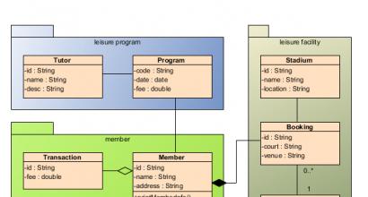
Class diagram:

Use case diagram:

ArgoUML
Supported charts:
- Class
- State
- Use case
- Activity
- Collaboration
- Deployment
- Sequence
Possibilities:
- Supports nine UML 1.4 diagrams
- Platform independent (Java 5+)
- UML 1.4 Standard Metamodel
- XMI support
- Export to GIF, PNG, PS, EPS, PGML and SVG
- Languages: EN, EN-GB, DE, ES, IT, RU, FR, NB, PT, ZH
- OCL support
- Forward, Reverse Engineering
Screenshot:

When developing software products, it is necessary to remember that the implementation process consists of at least three stages:
- design;
- implementation;
- testing;
Design is the main stage of software development. On the basis on which the program will be implemented.
One of the popular design tools is UML language. This language is universal and has the necessary methods and functions for generating the created circuit into a programming language. Using UML allows you to simplify the design stage and make it more convenient.
For UML design, there are special editors that can generate the designed diagram in one of the programming languages. Those. convert the created classes and methods designed in the UML editor diagram into one of the programming languages, for example, C++. After that, you will only need to implement the methods and use them.
EditorsUML
It is not possible to analyze all UML-based design tools; below are several frequently used editors.
1. Star UML
The UML editor for designing interconnected application classes is a CASE tool.
This editor is free and has a number of functions for designing interrelated classes and generating diagrams in one of the programming languages (C++, C#, Java).
UML editor StarUML is a package implemented in the Delphi programming language, open source, developed for Windows OS.
Supports UML 2.0 (extended to support the methodology ModelDrivenDevelopment) And Model Driven Architecture(building an abstract metamodel for managing and exchanging metadata (models) and specifying ways to transform it into supported programming technologies.
You can increase the functionality of the UML editor StarUML using plugins and modules. More details about using this program can be found in the manual / in Russian.
2. Apollo
Apollo is a module that supports UML design developed for Eclipse. One of the main advantages of this module is that the programmer has the opportunity to dynamically create and simultaneously edit model code in one environment (Eclipse).

The capabilities of this module allow reverse engineering in both directions; it supports Java 6, UML 2.1. Allows you to process higher-level diagrams in the hierarchy.
1. Rational Rose
Rational Rose UML editor for UNIX/Linux OS is a leader among visual modeling tools. The program is easy to use and is a fully integrated solution for software development, including Internet solutions.

One of the advantages of this program is its integration with the Microsoft Visual Studio environment. Rational Rose is a wide-ranging software as it provides the ability to implement projects using COM/ATL, XML, ADO MTS. Performs reverse engineering of JSP and ASP file semantics. Supports WinDNA and J2EE/SE/ME models.
This software can be used by software engineers, analysts (including business analysts), web developers, developers and database designers.
In custody
UML is a universal language for modeling software structure. Which is an integral part when designing a software structure, especially when using an object-oriented approach.